Showing posts with label Theory of machines. Show all posts

Monday, 4 February 2019

Flywheel Notes


Flywheel is an inertial energy-storage device, acts as a reservoir of energy, which stores energy during the period when supply of energy is more than requirement and release it during the period when supply is less than the requirement.
It does not control the speed variations caused by the varying load.


Speed Fluctuation


  • The difference between the maximum and minimum speed during a cycle is called the speed fluctuation and is equal to $ω_{max} - ω_{min}$.

  • The ratio of maximum fluctuation of speed to the mean speed is called coefficient of fluctuation of speed (Cs).
\[C_s = \frac{ω_{max} - ω_{min}}{ω}\]


  • The reciprocal of the coefficient of fluctuation of speed is known as coefficient of steadiness.

Energy Fluctuation

The kinetic energy Ek in a rotating system 
\[E_k = \frac{1}{2}Iω^2\]

Hence the change in kinetic energy ($e = \triangle E_k$) of a system can be written as

\[e = \frac{1}{2}I(ω^2_{max} - ω^2_{min})\]
\[e = \frac{(ω_{max} + ω_{min})}{2}I(ω_{max} - ω_{min}) = I(ω)(C_s ω) = I C_s ω^2\]
\[\boxed{I = \frac{e}{C_s ω^2}} \]


  • Coefficient of fluctuation Energy (Ce) is defined as
\[C_e = \frac{e}{work-done-per-cycle}\]


Turning Moment Diagram

  • Work done per cycle is = $T_{mean} * θ$.


Related Post:


Friday, 15 June 2018

Gear Train


A gear train is a combination of gears used to transmit motion from one shaft to another. The followings are  main type of gear trains:

  • Simple Gear Train
  • Compound Gear Train
  • Reverted Gear Train
  • Planetary or Epicyclic Gear Train

Speed Ratio and Train Value:


It is the ratio of the speed of driving gear to that of the driven gear. The reverse of the speed ratio is known as train value.
\[\boxed{Train\quad value = \frac{1}{Speed \quad ratio}}\]

1. Simple Gear Train


All the gear axes remain fixed relative to the frame and each gear on the separate shaft. 

Simple Gear Train

By gear rules: $ \frac{N_2}{N_1} = \frac{T_1}{T_2}$, $ \frac{N_3}{N_2} = \frac{T_2}{T_3}$, $ \frac{N_4}{N_3} = \frac{T_3}{T_4}$, $ \frac{N_5}{N_4} = \frac{T_4}{T_5}$

\[Train\quad value = \frac{N_5}{N_1} = \frac{N_5}{N_4 } * \frac{N_4}{N_3 }*\frac{N_3}{N_2 }*\frac{N_2}{N_1 } = \frac{T_4}{T_5 }*\frac{T_3}{T_4 }* \frac{T_2}{T_3 } * \frac{T_1}{T_2 }\]
\[Train\quad value = \frac{T_1}{T_5} = \frac{number \quad of \quad teeth \quad on \quad driving \quad gear}{number \quad of \quad teeth \quad on \quad driven \quad gear}\]

Note:
  • Two external gears of a pair always moves in opposite direction. For example gear 3 is anti CW then gear 4 is CW in direction.
  • All odd number gear(1,3,5) moves in one direction and all even number gear(2,4) moves in the opposite direction.
  • The intermediate gears have no effect on the speed ratio or train value therefore they are known as idlers.

2. Compound Gear Train


When a series of gears are connected in such a way that two or more gears rotate about an axis with the same angular velocity. 


\[Train\quad value = \frac{N_4}{N_1} = \frac{T_1*T_3}{T_2*T_4}  = \frac{product \quad of \quad number \quad of \quad teeth \quad on \quad driving \quad gear}{product \quad of \quad number \quad of \quad teeth \quad on \quad driven \quad gear}\]


3. Reverted Gear Train


It is a compound gear trian where input gear axis and output gear axis coincides. 


Reverted Gear Train
\[Train\quad value = \frac{N_4}{N_1} = \frac{T_1*T_3}{T_2*T_4}  = \frac{product \quad of \quad number \quad of \quad teeth \quad on \quad driving \quad gear}{product \quad of \quad number \quad of \quad teeth \quad on \quad driven \quad gear}\]
also,
\[r_1 + r_2 = r_3 + r_4\]
\[m_{12}[T_1 + T_2] = m_{34}[T_3 + T_4]\]
m is the module of the gear


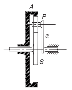
4. Planetary or Epicyclic Gear Train


Epicyclic Gear Train


  • Epicyclic gear train is the one in which the axis of some gears have relative motion. 
  • Large speed reductions are possible with epicyclic gears.
  • Important application of epycyclic gears are in transmission, computing devices.

Relative Velocity Method


$N_{pa}$ : Angular vel. of P relative to arm a = Np - Na

$N_{sa}$ : Angular vel. of S relative to arm a = Ns - Na
\[\frac{N_{pa}}{N_{sa}} = -\frac{T_s}{T_p}\]
\[\boxed{\frac{N_p - N_a}{N_s - N_a} = -\frac{T_s}{T_p}}\]


Tabulation Method


5. Sun and Planet


When an annular wheel is added to the epicyclic gear train, the combination is referred as Sun and Planet gear train.
Sun and Planet Gear Train

In general, S, A and a are free to rotate independently of each other. Table can be prepared:


References:


***
If you have any query, ask in comments.

Tuesday, 24 April 2018

CAM Follower-II


Terminology of Radial Cam


Base Circle


It is the smallest circle tangent to the cam profile drawn from the centre of rotation of the radial cam. The base circle decides the overall size of the cam and thus is fundamental feature.

Trace Point


The points on the follower which is required to trace the cam profile is known as trace point. For a roller follower, the trace point is at the roller centre.

Pitch Curve


The curve traced by trace point is known as pitch curve. It is parallel to the cam profile.

Prime Circle


It is the smallest circle that can be drawn so as to be tangential to the pitch curve, with its centre at the cam centre.

Pressure Angle


The angle between the direction of the follower movement and the normal to the pitch curve at any point is called pressure angle. It represents the steepness of the cam profile. Higher the pressure angle higher is side thrust and higher the chances of jamming the translating follower in its guide ways.

Pitch Point


It is the point on pitch curve at which pressure angle is maximum.

Lift (or) stroke


It is the maximum travel of the follower from its lowest position to the topmost position.

Follower Displacement Diagram


Angle of Ascent


It is the angle through which the cam turns during the time the follower rises.

Angle of Dwell


It is the angle through which the cam turns while the follower remains stationary at the highest or the lowest position.

Angle of Descent


It is the angle through which the cam turns while follower returns to the initial position.

Angle of Action


It is the total angle moved by the cam during the time between the beginning of rise and the end of return of the follower.


Force Exerted by Cam


The force exerted by a cam on the follower is always normal to the surface of the cam at the point of contact. The vertical component (F cosα) lifts the follower whereas the horizontal component(F sinα) exerts lateral pressure on the bearing. To reduce the lateral pressure, α has to be decreased which means making the cam surface more convex or longer but that reduces the velocity of follower. The minimum value of α can not be reduced from a certain value.


Kinematics:


Let's say s is the displacement of the follower and θ is cam angle.

Velocity of the follower = \( \dot s = \frac{ds}{dt} = w\frac{ds}{dθ}\)

Where $\frac{ds}{dθ}$ represents the slope or the steepness of the displacement curve at each position of cam angle.

Acceleration of the follower = \( \ddot s = \frac{d^2 s}{dt^2} = w^2\frac{d^2s}{dθ^2}\)


  • Higher value of acceleration means a higher inertia force.
  • The value of $\frac{d^2s}{dθ^2}$ is inversely proportional to the radius of curvature of the cam at different points along its profile. 

Third derivative is known as 'Jerk' and higher values of jerk are undesirable.
\[Jerk = \dddot s = = \frac{d^3 s}{dt^3} = w^3\frac{d^3s}{dθ^3}\]


***
If you have any query regarding this article, ask in comments.

Reference:


CAM Follower-I

  • A Cam is mechanical member used to impart desired motion to a follower by direct contact.
  • Cam- follower mechanism belong to higher pair mechanism.
  • It is used in automated machines, IC engines, machine tools, printing control mechanisms, textile weaving industries etc.
  • A driver member is known as cam.
  • A driven member is known as follower.
  • A frame is one which supports the cam and guides the follower.

Classification of cams

1. According to Shape


1.1 Wedge and Flat Cams


A wedge cam has a translational motion and follower can either translate or oscillate.


1.2 Radial or Disc Cams


A cam in which the follower moves radially from the centre of rotation of the cam is known as radial or disc or plate cam.


1.3 Cylindrical Cams


A cylinder has a circumferential contour cut in the surface and the cam rotates about its axis. The follower motion is either oscillating or reciprocating type. These cams are also called drum or barrel cams.


1.4 Spiral Cam


A spiral cam is face cam in which a groove is cut in the form of a spiral. It is used in computers.

1.5 Globoidal Cams


It has two types of surface i.e. convex and concave. It is used when moderate speed and angle of oscillation of the follower is large.


Classification of Follower

1. According to shape


1.1 Knife edge follower

The contacting end of the follower has a sharp knife edge. Its use is limited as it produces excessive wear of the contacting surface.

1.2 Roller Follower

It consists of a cylindrical roller which rolls on cam surface. At low speeds, the follower has pure rolling but at high speeds some sliding also occurs. The roller followers are extensively used where more space is available such as gas and oil engines.

1.3 Flat face follower

The follower face is perfectly flat. It experiences a side thrust due to the friction between contact surfaces of follower and cam.

1.4 Spherical face follower

The contacting end of the follower is of spherical shape which overcomes the drawback of side thrust as experiences by flat face follower.


2. According to Movement


2.1 Reciprocating Follower

In this type, as cam rotates the follower reciprocates or translate in the guides.

2.2 Oscillating Follower

The follower is pivoted at a suitable point on frame and the rotary motion of cam is converted into predetermined oscillatory motion of the follower.


3. According to location of line of movement


3.1 Radial Follower

The follower is known as a radial follower as a radial follower if the line of movement of the follower passes through the centre of the rotating of the cam.

3.2 Offset Follower

If line of movement of the follower is offset from the center of the cam shaft, the follower is known as offset follower.


PART-2


***
If you have any query regarding this article, ask in comments.

Monday, 12 February 2018

Inversion of Mechanism

Method of obtaining different mechanisms by fixing different links in a kinematic chain, is known as inversion of the mechanism.

Inversion of 4-Bar Mechanism

  • Crank-Crank Mechanism : Coupling rod of locomotive
  • Crank-Rocker Mechanism : Beam Engine
  • Rocker-Rocker Mechanism : Watt's indicator

Inversion of Slider-Crank Mechanism


  • First Inversion - link 1 is fixed  : Reciprocating engine

  • Second Inversion- link 2 is fixed : Rotary engine, Whitworth quick return mechanism
Rotary engine

  • Third Inversion - link 3 is fixed: Crank and slotted lever mechanism, Oscillating cylinder mechanism
Oscillating cylinder mechanism


Crank and slotted lever quick return motion mechanism

  • Fourth Inversion - link 4 is fixed: Hand pump, bull engine

Bull Engine                             
Hand pump


Inversion of Double Slider Crank

It has four binary links, two revolute pairs, two sliding pairs.
 
Double Slider Mechanism

  • Link 1 is fixed : Elliptical Trammel

  • Link 2 is fixed : Scotch yoke mechanism


  • Link 3 is Fixed : Oldham Coupling

Oldham coupling is used to connect two shaft which has lateral misalignment. 


Mechanism and Machines

Mechanism

A mechanism is a combination of rigid or restraining bodies so shaped and connected that they move upon each other with a definite relative motion. Example: slider crank mechanism, type write.

Machine

A machine is a mechanism or a collection of mechanisms which transmits and modifies the available mechanical energy into some kind of desired work.

Kinematic Pair

According to nature of contact

1) Lower pair

A pair is said to be a lower pair when it having surface or area contact between members.


2) Higher Pair

When a pair has point or line contact between members, it is called as higher pair. e.g. cam and follower pair, gears, wheel rolling on a surface.


Wrapping Pairs comprise belts, chains, and other such devices.


According to nature of Relative motion

  • Turning Pair: When one link can turn or revolve about a fixed axis of another link, the pair is known as turning pair. e.g. a shaft with collars at both ends fitted into a circular hole, the crankshaft in a journal bearing in an engine. A turning pair also has a completely constrained motion.
  • Sliding Pair: When two links have sliding motion relative to each other, the pair is  called sliding pair. e.g. piston and cylinder, ram and its guides in shaper.
  • Rolling Pair: When the link of a pair have rolling motion relative to each other. e.g. Ball and roller bearings. 
  • Screw Pair: If two mating links have turning as well as sliding motion between them. e.g. lead screw, nut of lathe.
  • Spherical Pair: When one link in the form of a sphere turns inside a fixed link. e.g. ball in socket.

According to mechanical constraint

  • Closed Pair: When two elements of a pair are held together mechanically. e.g., all lower pair and some of higher pair.
  • Open or Unclosed Pair: When two elements of a pair are not held together mechanically. e.g., cam and follower.

Types of Constrained Motions

  • Completely Constrained Motion: When motion between two elements of a pair is limited to a definite(single) direction irrespective of the direction of force applied, It is known as completely constrained motion. For example, the piston and cylinder (in a steam engine) form a pair and the motion of the piston is limited to a definite direction relative to the cylinder irrespective of the direction of motion of the crank.
  • Incompletely Constrained Motion: When the motion between the elements of a pair is possible more than one direction, then the motion is  called an incomplete constrained motion. e.g. cylindrical shaft in round bearing.
  • Successfully Constrained Motion: When motion between the elements of a pair is possible more than one direction but made to have motion only one direction by some other means. e.g. piston reciprocating inside an engine cylinder, shaft in foot step bearing.

Kinematic Chain


A kinematic chain is a series of links connected by kinematic pairs. The chain is said to be closed chain if every link is connected to at least two other links, otherwise it is called an open chain.

Condition for kinematic chain


l = 2P - 4
where, l = Number of link
             P = Number of pair

2J = 3l - 4
where, J = Number of binary joint
l = Number of link

  • If L.H.S. > R.H.S.  => Structure or frame or locked chain
  • If L.H.S. = R.H.S.  => Kinematic chain or constrained chain
  • If L.H.S. < R.H.S.  => Unconstrained chain


Types of Joins

  • Binary Joint :  It two links are joined at the same connection.
  • Ternary Joint : If three links are joined at the same connection. It can be considered as two binary joints.
  • If n number of links are connect at a joint, it is equivalent to (n - 1) binary joints.

Degree of Freedom (DOF)

It is the number of independent variables that must be specified to define completely the condition of the system.

  • DOF of a space Mechanism (3-D)
F = 6(L - 1) - 5P1 -4P2 -3P3 -2P4 - P5

F = Degree of freedom (DOF)
L = Total number of links
P1 = Number of pairs having one DOF
P2 = Number of pairs having two DOF
P3 = Number of pairs having three DOF
P4 = Number of pairs having four DOF
P5 = Number of pairs having five DOF

  • DOF of plane (2 D) mechanism (Grabbler Criterion)
F = 3(L - 1) - 2P1 - P2

L = Total number of links
P1 = Number of pairs having one DOF
P2 = Number of pairs having two DOF

  • Kutzback's Equation
F = 3(L - 1) - 2j - h

L = Total number of links
j = Number of binary joints
h = Number of higher joints
  • Grubler's Equation
          For those mechanism which have single degree of freedom and zero higher pairs.

3L  - 2j - 4 = 0


Four Bar Mechanism


Grashof's theorem states that a four-bar mechanism has at least one revolving link if


and all three mobile links will rock if    s + l > p + q


   Case         l+ s  vs  p + q      Shortest bar     Mechanism Type    
            <       Frame Double Crank
     2       <      Side Rocker Crank
     3       <      Coupler Double rocker
     4      =      Any Change Point
     5      >      Any Double rocker


Mechanical Advantage


Mechanical Advantage (M.A.) = Output force or torque / Input force or torque


Power Input = Power Output
T2w2     = T4w4


  • If α = 0  and 180 degree, w4 becomes zero thus MA will be infinity.
  • Extreme position of linkage is known as toggle position.
  • The angle β is called the "transmission angle"


Contact Form

Name

Email *

Message *